Tech Specs
STARPAK-61R-39SF-4-HD
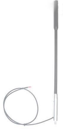
IRIDIUM Extreme Heavy Duty Helix High Gain Bull Bar Whip Antenna
BASIC DESIGN – The included mounting options are: (i) Rigid Mounted, or (ii) HD Spring Mounted(spring NOT included)
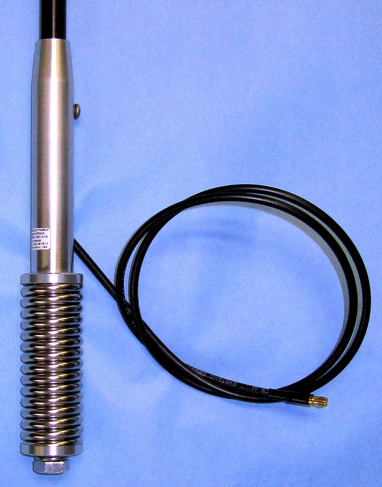
RIGID: Hex Nut with Flat & Spring Washer fixes the Threaded Spun Aluminum Boom Adapter securing the Aluminum Pole that supports the Antenna Radome
WITH SPRING: Bolt with Spring Washer fixes the Spring Mount, to a Threaded Spun Aluminum Boom Adapter securing the Aluminum Pole that supports the Antenna Radome
Overall Assembled Length from mounting base: Spring 107mm > Boom 140mm > Pole 370mm > Radome 170mm = Total of 787mm(31.0in)
WEIGHTS AND SHIPPING MEASUREMENTS
Item# 1. Weight of Antenna w/Boom Adapter and 1.0m(39in) cable tail, part# STARPAK-61R-39SF-4-HD: 346g(13.2oz)
TOTAL PRODUCT WEIGHT: 346g(13.2oz)
Shipping Tube Pack weight: 400g(14.1oz)
SHIPPING DIMENSIONS (of Shipping Tube Pack): Diameter 95mm(3.75in) x 870mm(34.3in)
SHIPPING WEIGHT (all items): 746g(27.3oz)
FIXED CABLE TAIL INFO – refer below for cable specifications
CABLE TAIL: Length is 1.0m(39in)
Cable Tail configuration: Side-exit from Boom Adapter, hermetically sealed
Cable Tail Type: is LMR195
Cable Tail connector: is Terminated with Gold SMA-Female by default.
Optional 4.5, 9, 12, 20 and 30m extended cable lengths available for longer installation runs
FIXED BOOM ADAPTER
Material: Spun Aluminum
Length: 140mm(5.5in) when assembled, or 158.75(6.25in) including 19mm(0.75in) Long 1/2-12 UNC/BSW Threaded Section
Diameter: Base at 25mm(1.0in) tapering to 20mm(0.8in) external to support the pole.
FIXED POLE
Material: Aluminum
Length: 370mm, supporting the Boom Adapter one end, and the Antenna radome at the other.
Diameter: 13mm(0.5in) Fixed within the Boom Adapter, base end, then the top end tapering out to 25mm(1.0in) to support the Antenna Radome
ANTENNA RADOME
Finish: Composite
Length: 165mm(6.5in)
Diameter: 25mm(1.0in)
ENVIRONMENTAL
Extreme Low to very High Temperature: -55°C to 85°C (-67°F to 185°F)
Wind Speed: 220kph(135mph)
Leakage: Hermetically Sealed
ELECTRICAL
Iridium Frequency: 1610 to 1626MHz
IRIDIUM Antenna Gain(bBic) in FS(Free Space)
@ 90° (ZENITH) 2.0
@ 10°………………. -2.5
@ 20°………………. -0.6
@ 30°………………. 0.7
@ 45°………………. 1.6
@ 70°………………. 1.7
Axial Ratio: 1(db) to 2(db)
Radiation Pattern: Hemispherical
Polarization: RHCP
VSWR: <1.5:1
DC Grounding: YES(Lightning Protection)
PROPERTIES
Material: 6061-T6 Aluminum Alloy base, Composite Radome
Features: Impact, Abrasion, UV, Solvent, and Skydrol Resistance, Fire Retardant
Finish: Skydrol Resistant Polyurethane Enamel base Iridite PER/ MIL-C-5441
NETWORK, FEDERAL & MILITARY SPECIFICATIONS
Manufactured in USA
Iridium certified product
DO-160D, DO-228, MIL-C-5541
MIL-E-5400, MIL-I-45208A, and SAEJ1455
Warranty: 2year no-quibble replacement, does not include corrosion or perishing to exposed cable or connectors, and does not include neglect, high impact, crushing, introduced damage
CABLE PROPERTIES
Fixed Cable Tail including integrated length: Manufacturer is Times Microwave, Type: LMR195, Integrated Length: 59in(1.498m), Loss dB Rating/meter: 0.50/m Cable Tail is Terminated with one Gold SMA-Female Connector Loss db Rating: 0.08dB max, Therefore this cable Tail Total loss = 0.83db
CONNECTOR OPTIONS
Email your required alternate Connector using the reference, as follows:
T: TNC, TB: TNC-Bulkhead,
S: SMA,
P: PINS
B: BNC
M: MCX, MM: MMCX, MMR: MMCX-R
N: N/N, NB: N-Bulkhead
SMC or SSMC or SSMB, SSMA
COLOUR OPTIONS
Black is supplied by default Email your required alternate colour using the reference, as follows:
Gloss White #17925(per USA FED-STD 595B) : Part# STARPAK-61R-39SF-1-HD
Lusterless Grey #36320(per USA FED-STD 595B) : Part# STARPAK-61R-39SF-2-HD
Olive Drab Green #34031(per USA FED-STD 595B) : Part# STARPAK-61R-39SF-3-HD
Lusterless Black #37038(per USA FED-STD 595B) : Part# STARPAK-61R-39SF-4-HD(supplied by default)
Desert Tan #FS23446 or 33446(per USA FED-STD 595B) : Part# STARPAK-61R-39SF-5-HD Compatible with all Iridium Satellite Products by Telstra, Beam, Pivotel, AST SatCom Global and other 3rd party suppliers
INSTALLATION INSTRUCTIONS
Overview: The antenna should be attached in a location that provides the clearest line of site to the sky and horizons minimizing obstructions or other interference. The top radome section should clear the roof line or overhead load(if any) to minimize interference. Ideally the antenna should be fitted on the bull bar/push bar of a vehicle, preferably on the offside corner so as not to obstruct the operators view This antenna does not require any ground plane. If available as most bull bars already have a fitting and hole for this type of antenna, if not, then a suitable hole or fixing plate will be required.
Step-by-step Instructions:
RIGID MOUNTING(no spring required): Disregard spring, and use pack containing nut, flat and spring washers.
SPRING MOUNTING(with spring to allow flexing): Use pack containing Bolt and spring washer.
1) Temporary A: Route and connect the cables temporarily between the antenna and communications device, and connect the cables.
2) Temporary B: Hand-tighten connectors, DO NOT HEAT-SHRINK or seal any connections,
3) Temporary C: Hold antenna upright, and MAKE A TEST CALL to confirm satisfactory operation of all components.
4) If all testing is complete, then move to the installation process as below
5) Locate and attach the Heavy Duty Spring to Boom if Spring Mounting is required(apply to Boom thread Loctite 243 or similar thread-locking compound)
6) Position the antenna vertically, before permanent fitting and observe line of sight to minimize any potential obstructions between the radome and sky horizons.
7) A horizontal / level mounting plate with a hole of 13mm(1/2in)diameter is required.
8) Minimum Mounting Plate Dimensions: Square or Round Plate of 50mm(2.0in) with minimum thickness of 2.7mm(3/32in or 0.11in) is required.
9) Mounting Hole Size: Use an existing mounting hole or drill a 13mm(1/2in) hole that will enable the antenna base threaded section to pass through.
10) Hole size: if oversize, use washers, however the hole size should not exceed the size of the hexagonal nut/bolt
11) Antenna Angle: Mount the antenna perpendicular to the surface, so the radome has an unobstructed clear view to the sky and horizons.
12) Secure the Antenna: Use washers and apply Loctite 243 or similar thread-locking compound to prevent vibration loosening
(DO NOT use any compound or foreign material on SMA/TNC or any RF cable connector or adapter threads)
13) Check intended cable route and identify sharp or protruding objects or sources of heat that may come in contact with the cable.
14) Choose an alternate route, or apply casing to protect the cable from potential damage.
15) Apply split conduit along entire cable run or house cable in cable tracks to protect cable.
16) Route and connect the cable/s between the antenna and communications device, and connect the cables.
17) MAKE A TEST CALL to confirm satisfactory operation of all components is maintained.
RIGID MOUNT INSTALLATION PACK – use when the HD Spring is not required
This 3pc pack Includes: 1x Hex Nut, 11mm(0.4in) Thick, 1/2in UNC/BSW Thread, 1x 1/2in Spring Washer, 1x 1/2in 1-14 Flat Washer
Requires Mounting Hole Size: 13mm(1/2in)
Requires Spanner/Wrench Size: 19mm(3/4in)
OPTIONAL – S/Steel HD Spring, Part# SPRING-61R-37-HD basic info – for full specs go to the part number
Spring Outer Dimensions: 37x107mm(1.4×4.2in)
Spring Base Internal Thread: 1/2-12 UNC/BSW
OPTIONAL – S/Steel Bull Bar Mount, Part# MOUNT-BM-50-KIT basic info – for full specs go to the part number
Hole Diameter: 16mm(0.62in)
Suitable for 30-50mm Bull bar or Pipe
OPTIONAL SPRING MOUNT INSTALLATION PACK – use for Bull Bar, Building, Pole, Marine Vessel etc.where Flexing is required
This 2pce pack includes: 1x Bolt, 25mm(1.0in) Long, 1/2-12 UNC/BSW Thread, and 1x Spring Washer, 3.5mm(0.14) Thick 1/2in
Requires Mounting Hole Size: 13mm(1/2in) Diameter
Requires Spanner/Wrench Size: 19mm(3/4in) – REFER MOUNTING GUIDE BELOW


