Product Description
IR-00-SBD3D1201-9603 Iridium 9603 SBD Developers Kit with Transceiver
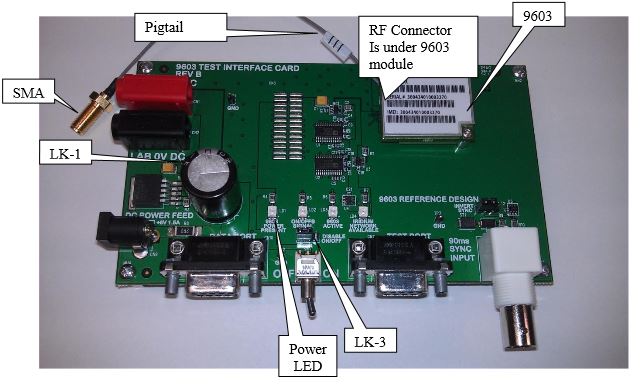
The Iridium 9603 Developer’s Kit includes a 9603 mounted onto a Test Interface Card (TIC).
This will allow for easy powering, control and interfacing to the 9603 and allow use of the 9603 with off the shelf hardware (e.g. with 5V DC power supply, Iridium-approved antenna, etc.)
Tech Specs
IR-00-SBD3D1201-9603
Iridium 9603 SBD Developers Kit with Transceiver
Power Supply
There are two methods DC power can be supplied to developer kit.
1. Either 5VDC from a laboratory bench power supply connected to the red & black jacks or
2. Use of a DC power block (6VDC 1.5A) to connected to the DC Power Feed jack (not provided).
Link LK1 should be set as follows:
o Connecting Pin 1 to Pin 2 supports a laboratory power supply (This is the default setting)
o Connecting Pin 2 to Pin 3 supports the DC Feed from an external power block
The “9603 Power Present” indicator should light when board power is on.
Size and mounting holes
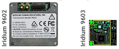
The 9603 Transceiver Module is 31.5mm x 29.6mm x 8.1mm and is intended to be mounted onto a PCB of the host system. For this purpose, two mounting holes are provided, intended for 2-56 screws of a suitable length for the mounting application.
In the Iridium 9603 Developer’s Kit, 2-56 x 1/2” buttonhead socket capscrews (McMaster 92949A081) are used to attach the 9603 Transceiver Module. A .050” hex wrench is required to remove the 9603 Transceiver module.
These screws attach through a 7/32” long hollow spacer (McMaster 92510A007) and into P-KF2-256-ET PEM nuts that are pressed into the 9603 TIC (Test Interface Card) boards.
Antenna Connector
The main RF connector for the Iridium 9603 is a Hirose U.FL-R-SMT-1 (mating cable SAMTEC MH113-MH1RP-01BJ1-0150 Pigtail). This provides the RF connection between the Iridium 9603 module and the motherboard.


